07
Oct
Fixed Tilt vs Adjustable Solar Mounting Structures
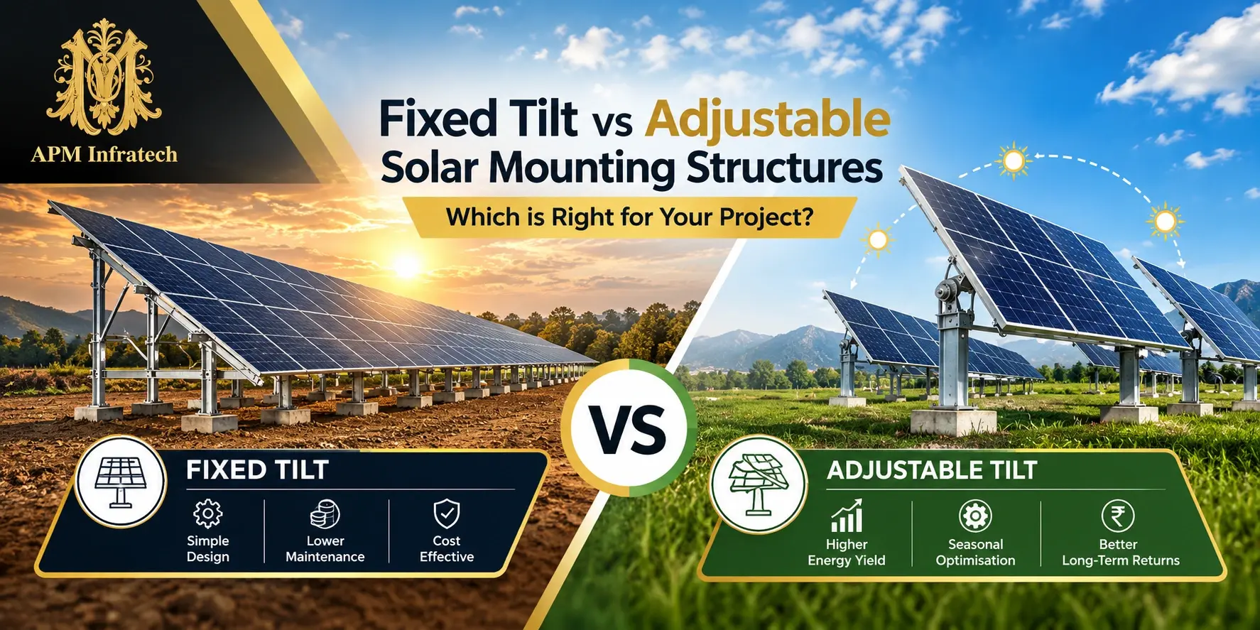
A fixed tilt solar structure holds modules at one engineered angle throughout the year. An adjustable structure allows the tilt to be changed manually at defined intervals. Fixed systems are normally simpler to design, install, inspect and maintain; adjustable systems may improve seasonal solar capture when the site, labour plan and structural design support safe repositioning. Neither option is automatically better. The correct choice depends on energy modelling, wind and snow loads, land or roof constraints, foundation capacity, module geometry, operating access and lifecycle cost.
For most buyers, the decision should begin with a project-specific energy and structural comparison rather than an assumed percentage gain. A change in tilt affects row spacing, shading, wind pressure, member forces, foundation reactions and access. Any extra generation must be compared with additional steel, hinges, locking points, labour, downtime and maintenance risk.
APM Infratech supplies solar structure solutions, including ground-mounted solar structures and rooftop solar structures. Project teams should share the layout, module data, site conditions and design basis before asking for a fixed or adjustable configuration.
Fixed Tilt and Adjustable Structures at a Glance
| Decision factor | Fixed tilt structure | Adjustable structure |
|---|---|---|
| Operating position | One engineered angle | Two or more planned tilt positions |
| Moving parts | Minimal | Hinges, pins, slots or locking points |
| Seasonal optimisation | Handled through chosen annual angle | Possible through scheduled repositioning |
| Structural checks | One operating geometry plus load cases | Every permitted position and transition condition |
| Routine labour | Inspection and maintenance | Inspection plus authorised adjustment |
| Error exposure | Lower | Incorrect angle or incomplete locking can create risk |
| Best fit | Low-complexity, repeatable projects | Sites with modelled benefit and controlled O&M |
The table describes design tendencies, not universal product characteristics. A robust adjustable system can be safer than a poorly engineered fixed system, and a fixed system can be uneconomic if its angle or spacing is wrong. Compare exact drawings, calculations, materials and operating procedures.
How a Fixed Tilt Solar Structure Works
A fixed tilt structure uses posts, columns, rafters, purlins, rails, bracing, clamps and foundations or roof interfaces to maintain a defined module plane. The angle and azimuth are selected during design, then the geometry remains unchanged during normal operation. The engineer checks the complete load path from modules and rails through connections and foundations into the supporting ground or building.
Simplicity is its main operational advantage. There are fewer adjustment joints to loosen, seize or be left partly engaged. Crews can standardise assembly, torque control and inspection. Fixed geometry also makes row-to-row shading and cable routing easier to preserve. These benefits matter on large sites where small additional tasks are multiplied across thousands of modules.
How a Manually Adjustable Solar Structure Works
A manually adjustable structure provides approved tilt positions, often through slotted members, pivot points, telescopic elements or alternative bolt holes. Trained personnel reposition the table at scheduled times, secure every locking point and record completion. The structure must remain stable during the adjustment process as well as in every final position.
Adjustability does not mean unrestricted movement. Permitted angles, sequence, crew size, weather limits, isolation requirements and torque values should be documented. Cable loops, connectors and earthing conductors must accommodate the full motion without tension, abrasion or loss of bonding. If a position is not covered by design calculations and instructions, it should not be used.
Energy Yield Is a Modelled Outcome
Tilting a module changes the solar irradiance received across seasons, but the net energy result also depends on latitude, climate, diffuse radiation, horizon, soiling, module temperature, inverter behaviour, mismatch, row shading and availability. A useful comparison models the same site, module, inverter and loss assumptions for both layouts.
Ask for annual and monthly energy estimates, not only a peak-season claim. The analysis should state the adjustment dates and angles assumed. If the O&M team misses an adjustment or leaves rows in different positions, the expected result may not be achieved. Sensitivity analysis can show whether the benefit remains worthwhile under realistic operating variation.
Structural Design Changes with Tilt
Changing angle alters the projected area exposed to wind and the distribution of uplift, compression and overturning forces. It can also change snow accumulation, drainage and torsional response. The designer should evaluate every allowed position using the applicable project criteria, including site wind speed, terrain, topography, importance, material properties and connection behaviour.
Do not compare structures by steel weight alone. Member section, grade, coating, unbraced length, hole position, weld quality, bolt class, foundation embedment and table geometry work together. A lighter system may be efficient engineering or may have less reserve; only calculations, drawings and verified material data can explain the difference.
Foundations and roof interfaces
For ground-mounted arrays, foundation selection may involve driven piles, micro-piles, concrete pedestals or other systems based on geotechnical investigation, pull-out and lateral capacity, corrosion exposure and installation tolerance. Adjustable positions can change reactions, so the foundation design must use the governing case.
For rooftops, the building engineer should review dead load, uplift, local attachment forces, waterproofing, drainage and roof warranty constraints. An adjustable mechanism that requires frequent access may not suit fragile sheets, congested roofs or locations without safe walkways. The host building, not only the solar frame, governs feasibility.
Row Spacing, Shading and Land Use
Higher winter tilt can cast a longer shadow, which may require wider row spacing to protect the selected shading window. Wider spacing can reduce DC capacity per unit of land. If rows are placed closer together, the energy model must include seasonal shading and mismatch. Adjustable systems therefore need a layout based on their maximum permitted tilt, not only the normal position.
On constrained land, a fixed angle may deliver more total project energy because it supports greater capacity, even if each module captures slightly less seasonal irradiation. On unconstrained land, wider spacing may be acceptable. Compare energy per module, energy per hectare and project economics rather than one metric.
Material and Corrosion Considerations
Solar structures may use pre-galvanised, hot-dip galvanised, coated steel, aluminium or other specified materials. Selection depends on environment, design life, forming and welding, contact between dissimilar metals, drainage and repair procedures. Moving or sliding interfaces on adjustable systems deserve particular attention because repeated motion can damage coatings or trap water.
Request the exact material grade, coating specification, thickness or mass requirement, fastener material and repair method. Review coastal, industrial, agricultural and high-humidity exposure separately. A generic statement such as corrosion resistant is not acceptance evidence.
Installation and Commissioning Comparison
| Stage | Fixed tilt focus | Adjustable focus |
|---|---|---|
| Survey | Levels, grid and obstructions | Same, plus movement clearance |
| Assembly | Geometry, bracing and torque | Pivots, locks, stops and orientation |
| Cabling | Support and service loops | Full-motion clearance and strain control |
| Alignment | Final tilt and azimuth | Every allowed position and repeatability |
| Handover | Drawings and torque records | Also adjustment method, schedule and lock checks |
Commissioning should confirm that the as-built geometry matches approved drawings. For an adjustable system, move a representative or specified sample through the authorised positions and check for binding, cable tension, unsafe reach and incomplete locking. Record the baseline position and label adjustment points clearly.
Operations and Maintenance Workload
A fixed system still requires inspection after severe weather and at planned intervals. Teams should look for loose fasteners, distortion, corrosion, foundation movement, damaged clamps, cable abrasion, vegetation or drainage issues. The maintenance plan should define inspection method and responsibility.
An adjustable system adds scheduled repositioning, supervision and records. Every row must reach the correct angle and every lock must be engaged. Work should be suspended in unsafe wind, rain, heat or electrical conditions. Sites need suitable access, tools, torque control and enough trained people to complete the change consistently.
Lifecycle Cost Comparison
Compare the installed and operating system, not only fabrication price. Include engineering, foundations, steel, mechanisms, labour, access equipment, adjustment time, inspection, spares, coating repair, downtime and expected energy difference. Discounted cash-flow assumptions should be visible so the buyer can test alternative schedules and energy prices.
A small predicted energy gain can be consumed by missed adjustments or recurring labour. Conversely, a well-designed adjustable system at an accessible site may justify its additional cost. The decision should be recorded with the assumptions that make it valid.
Project Suitability Guide
| Project condition | Usually favours fixed tilt | May support adjustable |
|---|---|---|
| Large utility array | Repeatability and low O&M complexity | Only with strong modelled benefit and process control |
| Industrial rooftop | Limited access and building constraints | Accessible robust roof with engineering approval |
| Remote site | Few visits and limited labour | Reliable local O&M and safe access |
| Seasonally variable load | Annual energy priority | Seasonal production has higher project value |
| High-wind exposure | Fewer configurations | All positions rigorously checked and controlled |
| Limited land | Potentially denser layout | Only if maximum-tilt spacing remains viable |
A Practical Selection Process
- Freeze module dimensions, table size, electrical layout and site boundaries.
- Obtain topographic, geotechnical, building and environmental inputs appropriate to the project.
- Model fixed and adjustable energy using identical loss and availability assumptions.
- Develop layouts using the governing tilt, shading window and maintenance access.
- Complete structural and foundation checks for every permitted operating condition.
- Price the complete installed scope and the recurring adjustment and inspection workload.
- Review safety, training, tools, records and responsibilities with the O&M team.
- Approve one controlled design and protect it through procurement and construction changes.
Documents to Request from the Structure Supplier
- General arrangement, table geometry and permitted tilt positions.
- Design basis, load assumptions and calculation approval route.
- Member, material, coating, bolt, clamp and foundation specifications.
- Module compatibility and clamp-zone confirmation.
- Fabrication, inspection, coating-repair and traceability records.
- Installation method, torque schedule and as-built acceptance checklist.
- For adjustable systems, safe adjustment instructions and locking verification.
- Warranty scope, exclusions, maintenance requirements and spare parts.
Common Decision Mistakes
- Selecting adjustable tilt from a generic generation percentage without site modelling.
- Designing row spacing for one angle while operating at a steeper position.
- Ignoring wind loads during adjustment or at the maximum tilt.
- Comparing steel weight without checking grade, section, bracing and foundations.
- Assuming rooftop access is suitable for repeated seasonal work.
- Leaving adjustment dates, crew responsibility and lock checks undefined.
- Changing module dimensions after structure design without revalidation.
- Treating catalogue claims as a substitute for project calculations.
Worked Example for an Industrial Solar Project
An industrial buyer is comparing a fixed rooftop layout with a manually adjustable alternative. The energy model shows a seasonal advantage for the adjustable option, but the maximum tilt increases row spacing and reduces the number of modules that fit. Roof access is limited and production cannot be interrupted for frequent work.
The team compares total annual energy for the final capacities, not per-module output. It also prices walkways, labour, movement-safe cabling and structural reinforcement. The fixed layout produces the stronger lifecycle case because it fits more capacity and requires less roof access. At another accessible ground site with ample land and seasonal power value, the result could be different.
Quality Control from Fabrication to Handover
Quality control should connect approved drawings to actual members and connections. Check incoming material identification, section dimensions, hole positions, cut edges, weld preparation, coating condition, fastener grade and packing. Templates and jigs can improve repetition, but inspection must still confirm that tolerances support assembly without forced alignment.
Site receiving checks should separate transit damage from fabrication non-conformance. Do not repair a damaged coating, enlarge a hole or substitute a bolt without an approved method. Record batch or heat references where the project requires traceability, and preserve inspection documents with the final as-built package.
For adjustable structures, quality checks should include pivot alignment, movement clearance, stop positions, pin retention and locking engagement. A mechanism that works on one table may bind after accumulated site tolerances. Commissioning should sample enough tables to provide confidence in the full installation and should close every defect before seasonal operation begins.
Change Control After Design Approval
Module supply changes are common, but a new module can alter length, width, weight, clamp zones and electrical layout. The structure supplier and designer should review the new data before fabrication or installation continues. The same discipline applies to changes in table size, pile length, steel grade, coating, row spacing or cable route.
Maintain one controlled set of drawings, calculations and bills of material. Site teams should not combine details from different revisions. A clear request-for-information process allows construction issues to be resolved without creating undocumented geometry that later complicates inspection, warranty or repowering.
Plan for Repowering and End-of-Life Work
A solar structure may remain in service when modules or inverters are replaced. Buyers should consider whether future modules with different dimensions or loads can be accommodated, but they should not assume universal compatibility. Repowering requires a fresh structural, clamp, electrical and foundation review.
Also plan safe disassembly, material segregation and access for major repairs. Bolted modular systems may support replacement, yet seized fasteners, hidden corrosion or undocumented field changes can increase effort. Accurate as-built records and maintenance history preserve options across the asset life.
Where APM Infratech Fits in the Evaluation
The live APM website describes design, fabrication, installation and solar structure support across several product categories. Review About APM Infratech and its solar structure products for current scope. Buyers should still verify exact capacity, certification, warranty, design responsibility and delivery commitments for their quotation.
Frequently Asked Questions
1. What is a fixed tilt solar structure?
It supports solar modules at one engineered angle for normal operation. The angle and complete load path are fixed during design.
2. What is an adjustable solar mounting structure?
It provides defined positions that authorised personnel can change manually. Every position and the adjustment process need engineering control.
3. Does adjustable tilt always produce more electricity?
Not always at project level. The result depends on site radiation, shading, row spacing, installed capacity, losses and whether adjustments occur as modelled.
4. Which option is cheaper?
Fixed tilt is often simpler, but price depends on material, foundations, layout and scope. Compare installed and lifecycle costs for the exact project.
5. Can adjustable structures be used on rooftops?
They can be considered only when the building, access, waterproofing, wind loads, movement clearance and safe work method support them.
6. How often is an adjustable structure moved?
The schedule is project-specific. It should come from energy modelling, manufacturer instructions and a safe O&M plan.
7. Does the highest tilt require wider row spacing?
Often it creates longer shadows, so layout analysis should check the maximum permitted tilt and selected shading window.
8. Which system has lower maintenance?
Fixed tilt normally has fewer movement and locking points, although both types require planned inspection.
9. Can the angle be changed without an engineer?
Only within approved positions and instructions. Unauthorised angles can invalidate structural, shading and cable assumptions.
10. What site data is needed for selection?
Typical inputs include module data, layout, location, wind criteria, terrain, soil or roof data, corrosion exposure, access and energy objectives.
11. Should buyers compare structure weight?
Weight is only one indicator. Section efficiency, material grade, connections, bracing, coating and foundations determine performance.
12. What should be included in the supplier quotation?
Request the exact configuration, materials, design scope, foundations or interfaces, accessories, installation, documents, warranty and exclusions.
Choose the Tilt Strategy That Improves the Whole Project
The strongest choice is the structure that delivers dependable energy, safe loads, practical installation and manageable O&M over the project life. Share the module datasheet, site location, layout, ground or roof information, target capacity, corrosion environment and operating plan with APM Infratech. Review the company’s solar structure rangeand use the APM Infratech contact page to request a project-specific fixed versus adjustable assessment rather than relying on a generic tilt recommendation.