14
Oct
Solar Structure Load Calculation: A Beginner’s Guide
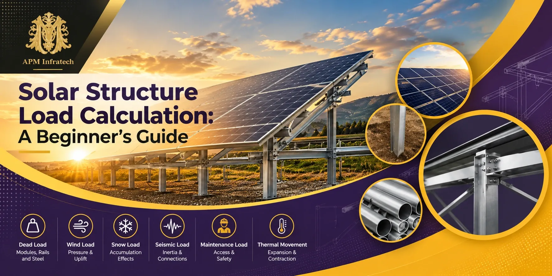
Solar structure load calculation is the engineering process used to determine the actions a mounting system and its supporting building or foundation must resist. It starts with permanent weight and then evaluates environmental and operational actions such as wind, snow where relevant, seismic effects, maintenance access and temperature movement. The engineer follows each load through modules, rails, purlins, rafters or posts, connections, anchors and finally the roof or ground foundation.
The calculation is not a universal spreadsheet in which project capacity is the only input. A 500 kW rooftop and a 500 kW ground-mounted array can have very different geometry, exposure, height, soil, support spacing and failure modes. APM Infratech lists a range of solar structure solutions for rooftop, ground and industrial applications; project design still requires verified inputs and code-based review by the responsible engineer.
The main loads on a solar mounting structure
| Load or action | Typical source | Why it matters |
|---|---|---|
| Dead load | Modules, rails, steel, fasteners, trays and fixed equipment | Creates permanent force in members, roof and foundations |
| Wind load | Pressure and suction on exposed module surfaces | Often controls uplift, anchors, bracing and edge zones |
| Snow or rain-related action | Accumulation or ponding where applicable | Adds vertical load and may be uneven |
| Seismic action | Movement of the supporting ground or building | Creates inertia and connection demands |
| Maintenance load | Workers, tools and temporary access | Affects local members and safe service access |
| Thermal movement | Expansion and contraction of long components | Influences joints, slots, stress and alignment |
Dead load
Dead load includes the self-weight of every permanent component: modules, mounting rails, purlins, primary frames, fasteners, ballast, cable trays and fixed electrical equipment supported by the structure. Use confirmed product masses and actual quantities, not an early allowance after procurement has changed. For rooftops, the existing roof and primary building structure must be checked for the additional reactions and their distribution.
Wind load
Wind can push down, slide the array or create uplift. Pressure depends on site wind data, terrain or exposure, height, building geometry, array tilt, gaps, edge distance and pressure zones. Roof corners and perimeters can face higher local suction than interior areas. Ground arrays also experience shielding and row interaction. These effects are defined through the applicable design method; a single force per square metre copied from another site is not a safe substitute.
Snow, rain and drainage effects
Where snow is relevant, the engineer considers ground snow information, roof shape, drifting, sliding and unbalanced accumulation. In other climates, drainage and ponding may be more important for roofs. A mounting layout must not obstruct drainage or create debris traps. Solar modules do not automatically strengthen the roof beneath them, and ballast can add significant permanent weight even when it avoids penetrations.
Seismic and dynamic actions
Seismic design relates component mass to the motion and behaviour of the site or supporting building. Connections and bracing require a continuous load path. Dynamic effects can also arise from wind-induced vibration or flexible members. The need for detailed analysis depends on the structure and governing requirements. These checks should not be reduced to adding a small percentage to gravity load without an engineering basis.
Inputs required before calculation
- Project location, coordinates, elevation and governing approval context.
- Rooftop or ground-mounted system, capacity, module dimensions and mass.
- Tilt, orientation, table size, row spacing and clearance above roof or ground.
- Material grades, coatings, member shapes, connection types and support spacing.
- Building drawings and structural survey for rooftop projects.
- Topographic, geotechnical and foundation information for ground systems.
- Design life, exposure, corrosion environment and maintenance assumptions.
- Applicable design codes, client criteria and authority requirements.
Input quality controls calculation quality. Record the source, revision and approval status of each parameter. If a module size, tilt or table layout changes, the affected wind area, mass, connections and reactions may also change. A calculation register should show which assumptions remain open and prevent preliminary values from silently becoming final.
A simplified calculation workflow
1. Define geometry and supports
Create an analysis model or calculation scheme showing modules, rails, secondary members, main frames, bracing, posts, anchors and foundations. Mark spans, cantilevers, member orientation and restraint. The structural model must reflect how the installed connection behaves; assuming a rigid joint where a slotted or flexible connection exists can produce misleading force distribution.
2. Calculate permanent weights
Multiply the mass of each repeated component by its quantity and convert it into forces at the appropriate locations. Include accessories and ballast, then calculate reactions at roof attachments or foundations. Check both overall load and local concentration. A roof may have enough total capacity while a thin sheet, purlin or small attachment area is locally overstressed.
3. Determine environmental actions
Use project location and the applicable method to establish wind, snow and seismic inputs. Apply pressure to the correct tributary area and direction. Distinguish downward pressure from uplift and consider zones or load cases that create different reactions. Environmental actions should be documented so another engineer can trace the source and reproduce the result.
4. Form load combinations
Loads do not simply add at full value in every situation. The governing standard defines combinations and factors for strength and serviceability. A downward case may control bending, while an uplift case controls anchors and a service case controls deflection. The engineer should review all relevant positive and negative directions and not report only the combination producing the largest vertical reaction.
5. Analyse members and load paths
Determine axial force, shear, bending, torsion and combined effects in each member. Slender elements may require buckling checks. Thin cold-formed sections can have local or distortional behaviour not captured by a simple gross-section stress calculation. Deflection and rotation should be limited so modules, clamps and cables remain functional and drainage or alignment is not compromised.
6. Design connections and anchors
Bolts, screws, clamps, welds, base plates and anchors transfer the forces between elements. Check edge distance, spacing, bearing, tear-out, slip, pull-out, shear, tension interaction and installation tolerances as relevant. Module clamp positions must follow the approved module documentation. The strongest rail cannot compensate for an unverified connection into a roof sheet or weak substrate.
7. Check the supporting building or foundation
For a rooftop, trace reactions into roof sheeting, purlins, trusses, beams, columns and foundations as required. For ground-mounted structures, check foundation bearing, uplift, sliding, overturning and lateral response using site soil data. APM provides pages for industrial solar structures and ground-mounted solar structures the selected arrangement must still be verified for the actual supporting condition.
A simple conceptual example
Consider one table supporting several modules. The engineer first totals module and steel weights and distributes them to rails and frames. Wind pressure is applied over the module area, producing downward, lateral and uplift cases. Each frame reaction is then transferred into posts and foundations or roof attachments. The calculation compares member strength, deflection, connection capacity and foundation response across the prescribed load combinations.
The example explains the sequence but does not provide design values. Changing table height, tilt, module gap, edge location, terrain or support spacing changes the result. Even adjacent arrays can have different pressure zones. Beginner calculations should therefore be used to understand load paths and review supplier submissions, not to authorize fabrication without qualified engineering.
Rooftop and ground-mounted calculations differ
| Design issue | Rooftop system | Ground-mounted system |
|---|---|---|
| Supporting condition | Existing sheet, purlin or building frame | Posts, piles or foundations in soil |
| Common constraint | Existing capacity, waterproofing and attachment | Geotechnical response, tolerances and terrain |
| Wind focus | Building edge zones and roof interaction | Row exposure, clearance and array geometry |
| Construction interface | Roof access and leak prevention | Survey, driving/drilling and foundation QA |
Rooftop projects require reliable as-built information and often a structural survey. Attachment layout should align with capable members and preserve waterproofing. Ballasted systems replace penetrations with added mass and friction assumptions that must be verified. Ground systems need survey control and geotechnical inputs; refusal, weak layers or variable soil can change the pile or foundation strategy.
APM also lists solar rooftop structure options among its product categories. Buyers should ask whether the proposal includes only fabricated members or also site measurement, structural design, connection engineering, installation and as-built documentation. Scope clarity prevents a catalogue arrangement from being mistaken for a completed project design.
What to check in a supplier calculation package
- Project name, location, drawing number, revision and design responsibility are clear.
- Module, layout, member, material and support inputs match the latest drawings.
- Load sources, directions, zones and combinations are traceable.
- Member utilization and serviceability results are reported, not only reactions.
- Connections, base plates, anchors and foundations are checked.
- Software outputs are supported by model description and engineering review.
- Assumptions, exclusions and required field verification are stated.
- Calculation, drawings and bill of materials share the same revision.
Common calculation mistakes
Frequent mistakes include using generic wind pressure, ignoring roof edge zones, omitting cable trays or ballast, applying loads to the wrong tributary area, checking members but not connections, assuming every support shares load equally, and using soil capacity without a site report. Another serious error is changing member thickness or hole patterns during procurement without revising the calculation.
Software does not remove the need for engineering judgement. An attractive utilization ratio can come from incorrect restraints, units, load direction or member properties. Independent review should focus on the model, load path and assumptions before reviewing colourful output pages. The About APM Infratech page can support a supplier capability review, but project-specific calculations and approvals remain essential.
How beginners can review a load take-down
A load take-down follows force from a surface to progressively larger supporting elements. Begin with pressure on one module or a defined module group. Transfer that force to the clamps, then to the rail or purlin using its tributary width. Continue through the main frame, bracing, post, base plate, anchors and foundation. At every interface, the incoming and outgoing forces should be consistent after allowing for geometry and direction. This simple trace often reveals a missing connection check or a reaction that was never carried into the supporting structure.
Use clear units throughout and perform rough reasonableness checks. Total permanent reactions should broadly reconcile with the installed weight, and paired support reactions should reflect the applied load and eccentricity. Under uplift, confirm the sign and ensure the anchor or ballast calculation uses the same governing reaction shown in the analysis. These checks do not replace the detailed model, but they help reviewers catch decimal, unit and load-application errors before fabrication.
From calculation to installation quality
Design assumptions must reach the site through controlled drawings, material identification and inspection. Verify member grade and coating, thickness, hole locations, fastener type, torque or installation method, bracing, embedment and alignment. Substitutions need engineering approval. For rooftop work, confirm attachments engage the intended structural member and that waterproofing treatment follows the approved detail.
Handover should include approved calculations, fabrication and erection drawings, material certificates, inspection records, anchor or pile test evidence where specified, nonconformance closure and as-built information. APM’s project portfolio can be reviewed for solution context; buyers should request evidence relevant to their structure type and project conditions.
Frequently Asked Questions
1. Can I calculate a solar structure using only project capacity?
No. Capacity does not define geometry, height, tilt, exposure, supports, material, soil or building condition, all of which can control structural demand. Project calculations must be completed and signed by a qualified structural engineer using verified site data, the selected system and applicable codes and approval requirements.
2. Which load usually governs a solar structure?
It depends on the project. Wind uplift often controls attachments and foundations, while gravity, snow, seismic, buckling or serviceability can control other components. Project calculations must be completed and signed by a qualified structural engineer using verified site data, the selected system and applicable codes and approval requirements.
3. What is tributary area?
It is the portion of loaded surface whose force is assigned to a particular member or support. Defining it correctly is essential when converting pressure into member loads. Project calculations must be completed and signed by a qualified structural engineer using verified site data, the selected system and applicable codes and approval requirements.
4. Why are roof edge zones important?
Wind suction can be higher near building edges and corners. The applicable method may require different pressures or attachment spacing in those zones. Project calculations must be completed and signed by a qualified structural engineer using verified site data, the selected system and applicable codes and approval requirements.
5. Does a ballasted system need structural calculation?
Yes. Ballast adds permanent roof load and relies on verified sliding, uplift and overturning behaviour, while the existing roof capacity and drainage must also be checked. Project calculations must be completed and signed by a qualified structural engineer using verified site data, the selected system and applicable codes and approval requirements.
6. Is soil bearing capacity enough for ground-mounted foundations?
No. Design may also require uplift, lateral, settlement, variability, corrosion and installation considerations based on suitable geotechnical information. Project calculations must be completed and signed by a qualified structural engineer using verified site data, the selected system and applicable codes and approval requirements.
7. Should bolts and clamps be checked separately?
Yes. Connections transfer load between members and may govern through tension, shear, slip, bearing, pull-out or combined effects. Project calculations must be completed and signed by a qualified structural engineer using verified site data, the selected system and applicable codes and approval requirements.
8. What is a load combination?
It is a prescribed combination of actions and factors used to check strength or serviceability under credible simultaneous conditions. Project calculations must be completed and signed by a qualified structural engineer using verified site data, the selected system and applicable codes and approval requirements.
9. Why is deflection checked if the member is strong enough?
Excess movement can damage modules, loosen connections, affect drainage, misalign arrays or create vibration even before material strength is reached. Project calculations must be completed and signed by a qualified structural engineer using verified site data, the selected system and applicable codes and approval requirements.
10. Can supplier software output replace signed calculations?
Software is a tool. The model, inputs, loads, combinations, connections and results still require competent engineering review and project approval. Project calculations must be completed and signed by a qualified structural engineer using verified site data, the selected system and applicable codes and approval requirements.
11. When must a calculation be revised?
Revise it when location, geometry, module, tilt, supports, materials, connections, loads or supporting conditions change in a way that affects the design. Project calculations must be completed and signed by a qualified structural engineer using verified site data, the selected system and applicable codes and approval requirements.
12. What should a buyer send for a structural proposal?
Send location, survey, layout, module data, capacity, tilt, roof drawings or geotechnical data, design criteria, corrosion environment, scope and approval requirements. Project calculations must be completed and signed by a qualified structural engineer using verified site data, the selected system and applicable codes and approval requirements.
Make Every Reaction Traceable from Module to Foundation
A dependable solar structure load calculation connects verified site data to environmental actions, load combinations, member checks, connections and the supporting roof or foundation. APM Infratech can review the project layout, structure type, material scope and available site information before preparing a technical-commercial proposal. Use the APM Infratech contact page to share drawings and request the required engineering and supply scope.